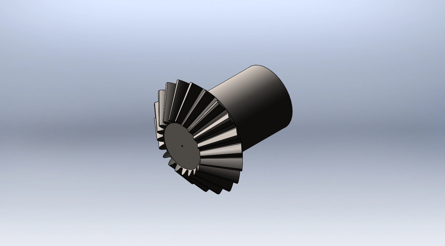
Autorickshaw differential & foot brake
I calculated the design parameters for the differential and foot brake, then modeled the differential parts and assembly in SOLIDWORKS.
January 2025
01Design requirements
| Parameter | Value |
|---|---|
| Engine power | 6.5 kW at 4000 rpm |
| Differential ratio | 4.2:1 |
| Maximum speed | 50 km/h |
| Vehicle mass / payload | 400 kg / 500 kg |
| Rear wheel radius / track | 0.25 m / 1.2 m |
| Stopping time | 5 s |
| Incline | 10° |
02Bevel gear geometry
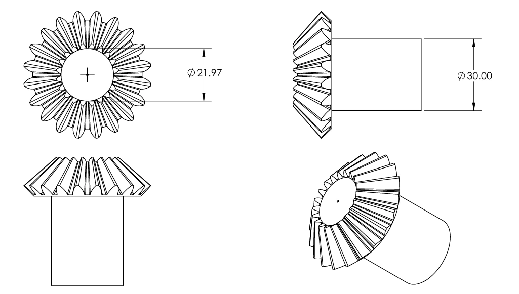
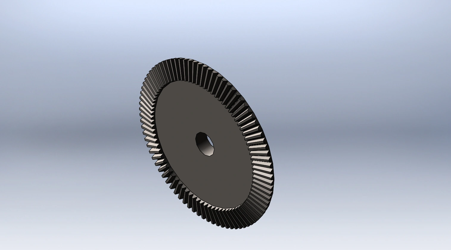
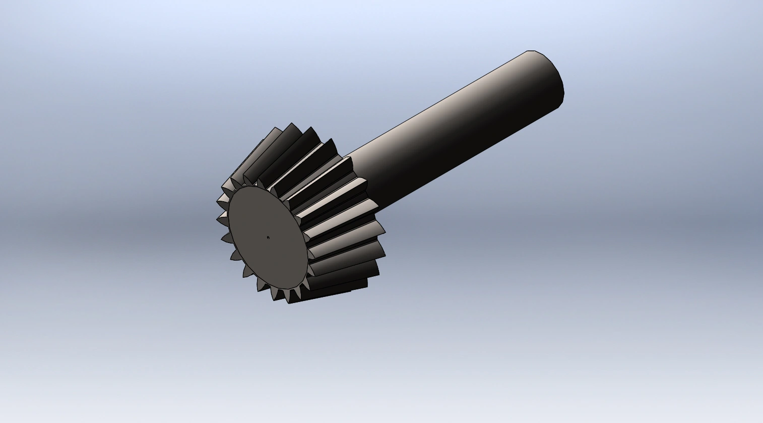
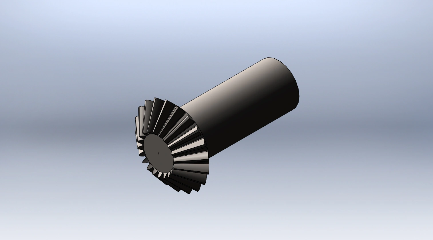
I selected a 20-tooth pinion and an 84-tooth gear, with a 2.5 mm module and 25 mm face width.
Using 4000 rpm at the pinion:
03Gear design factors
I used carburized and case-hardened steel, with a bending design factor of 3.
| Factor | Pinion | Gear |
|---|---|---|
| Bending life YNT | 0.862 | 0.903 |
| Pitting life ZNT | 1.00 | 1.09 |
| Bending geometry YJ | 0.270 | 0.223 |
| Contact geometry ZI | 0.094 | 0.094 |
| Temperature Kθ | 1 | 1 |
| Lengthwise curvature Yβ | 1 | 1 |
For transmission accuracy number \(Q_v=6\):
04Gear bending and contact stress
Bending
I used \(K_A=1\) and an allowable bending stress number of 205 MPa.
| Result | Gear | Pinion |
|---|---|---|
| Bending stress | 36.27 MPa | 29.95 MPa |
| Permissible stress at SF = 3 | 57.40 MPa | 54.79 MPa |
| Bending factor | 4.75 | 5.49 |
\(W_t\) is in N; \(b\) and \(m\) are in mm.
Contact stress model
I used a contact stress number of 1380 MPa and \(S_H=\sqrt3\). Here, \(Z_E\) is the elastic coefficient and \(Z_W\) is the hardness-ratio factor.
05Drum brake geometry
I used a 125 mm drum radius, 30 mm shoe width and friction coefficient of 0.32.
\(a\): distance from drum centre to shoe pivot; \(c\): actuation moment arm.
06Brake force and torque
Vehicle braking requirement
For a 900 kg loaded vehicle stopping from 50 km/h in five seconds:
Assuming equal braking at the two rear wheels and neglecting drag and rolling resistance:
Shoe forces
I used a sinusoidal pressure distribution, \(p(\theta)=P_a\sin\theta/\sin\theta_a\).
The minus sign applies to the leading shoe and the plus sign to the trailing shoe. \(P_a\) is peak lining pressure; angular integration uses radians.
Shoe pressure example
For an assumed \(P_a=134.60\) kPa:
| Quantity | Value |
|---|---|
| Normal moment MN | 82.79 N m |
| Friction moment Mf | 25.57 N m |
| Leading-shoe actuation force | 269.90 N |
| Shoe torque Ts | 32.06 N m |
07Differential models and drawing