Bursting pressure test setup
I sized the power screw, frame and handle for a hydrostatic pipe test setup and built the assembly in SOLIDWORKS.
May 2024
01Design requirements
| Parameter | Value |
|---|---|
| Pressure | 10 bar = 1 MPa |
| Maximum pipe diameter | 225 mm |
| Material | AISI 1020 cold-drawn steel |
| Yield strength used | 390 MPa |
| Design factor | 3.5 |
02Power screw load and torque
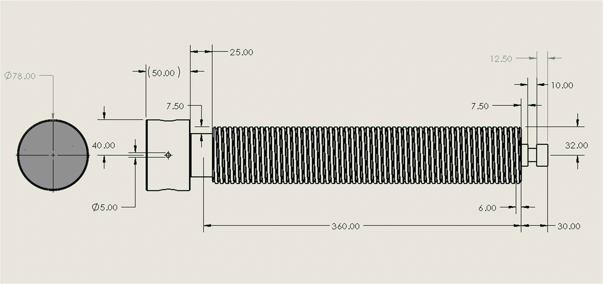
I selected a nominal diameter of 64 mm and a 6 mm pitch for the single-start screw. The axial load was based on the maximum pipe diameter.
I assumed a thread friction coefficient of 0.125. The torque calculation considered thread friction.
\(p\): fluid pressure; \(p_s\): thread pitch; \(d_m\): mean diameter; \(d_r\): root diameter; \(l\): lead.
03Screw stresses
I included torsion, axial compression and thread-root bending, assuming that one thread carried 38% of the axial load.
Using the assumed stress components \(\sigma_x=\sigma_b\), \(\sigma_y=\sigma_a\), \(\sigma_z=0\) and \(\tau_{yz}=\tau\):
04Base and plate sizing
Base member
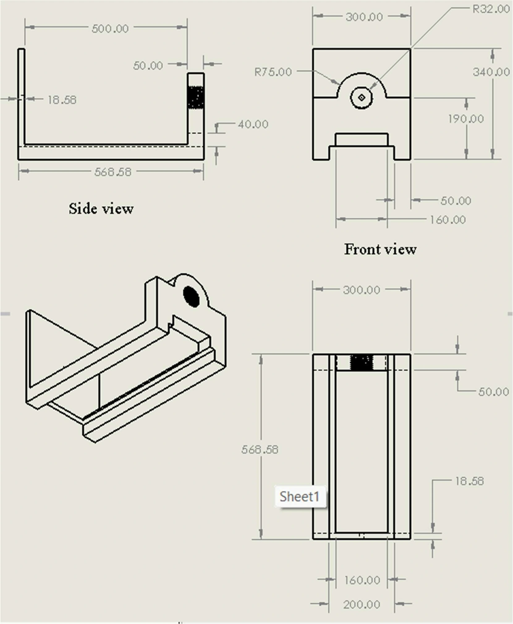
I treated the base as two load-sharing rectangular members, using \(H=300\) mm and \(b=70\) mm.
| Height h | Stress | Factor |
|---|---|---|
| 47 mm | 133.84 MPa | 2.91 |
| 50 mm | 119.28 MPa | 3.27 |
| 52 mm | 110.91 MPa | 3.52 |
I selected a 70 × 52 mm section for the base-member calculation.
Plate sizing model
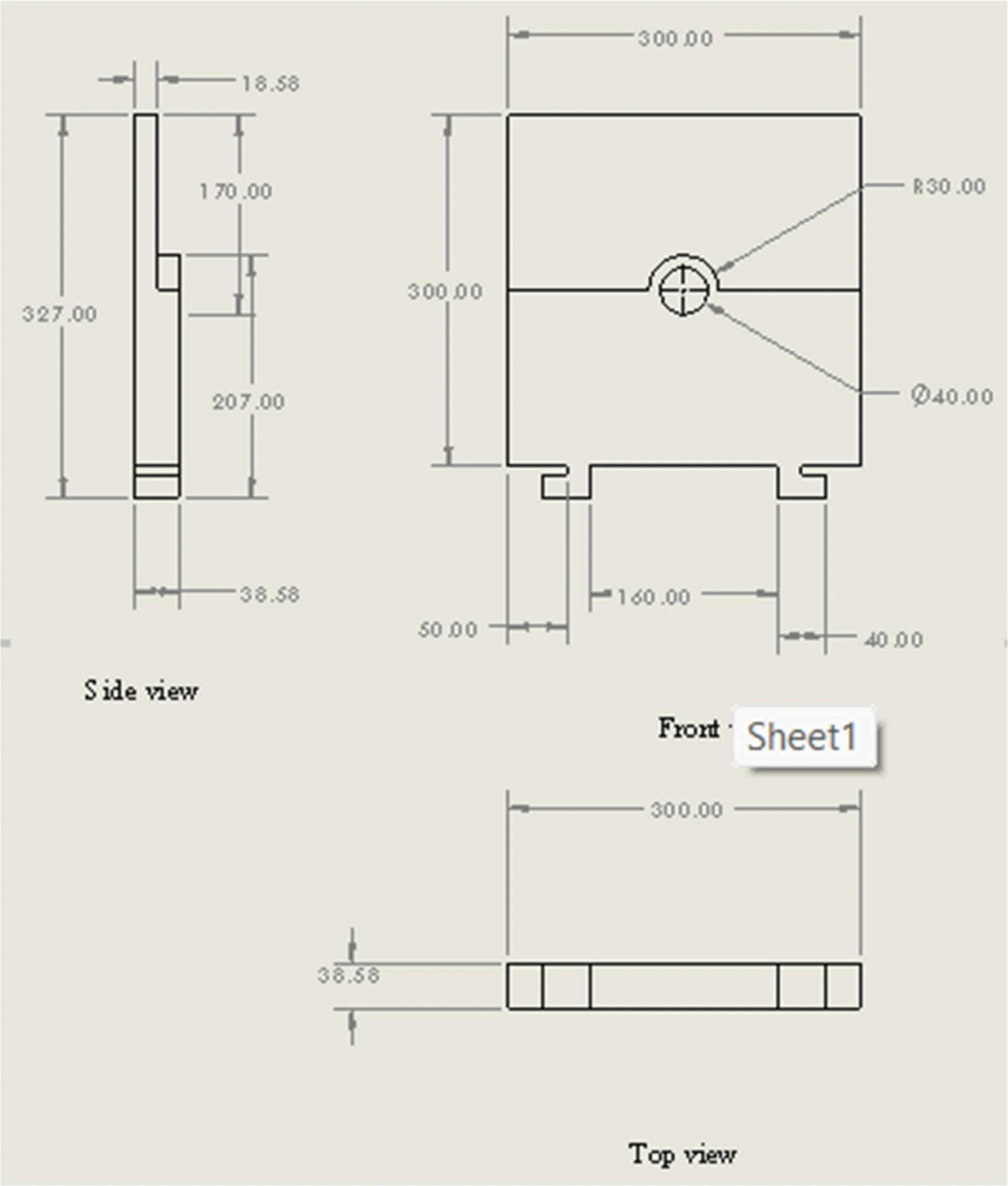
For the plate-sizing approximation, \(R_0\) represents the loaded radius. I used an 18.58 mm plate thickness in the CAD drawings.
05Handle sizing
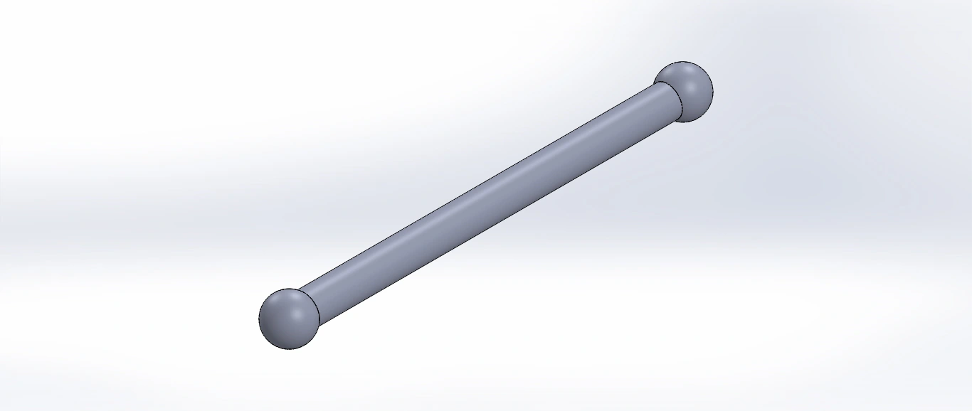
I compared lever lengths from 200 to 400 mm and selected a 350 mm handle.
| Parameter | Value |
|---|---|
| Lever arm L | 350 mm |
| Screw radius rs | 32 mm |
| Hand force Fh | 543.7 N |
| Calculated diameter at n = 3.5 | 25.10 mm |
| Modeled handle diameter | 25 mm |
06Dimensioned drawings